Geiger Counter Wiring Diagram
Geiger Counter Circuits and Radioactivity. The power MOSFET IRF830 switches the current on and off to the primary windings of the mini step-up transformer.
 The Free Information Society Geiger Counter Electronic Circuit Schematic Circuit Diagram Electronics Circuit Electronics
A GEIGER COUNTER is a Geiger-Muller tube opperated in the Geiger voltage region for the tube.
Geiger counter wiring diagram. Model 3 Technical Manual Section 1 Ludlum Measurements Inc. Any Geiger-Mueller GM detector offered by Ludlum Measurements will. Next I cut the holes for the switch and drill a hole for the tube.
Figure 7 Basic system diagram of a full-fledged Geiger-Counter Schematics around GM tubes are mainly related to the precision high voltage generation. The following diagrams should give you the idea. I fixed this by simply chiseling away at it.
DIY Geiger Counter - Page 4 Geiger Counter Schematic. CLOVERLEAF PORT METERFACE 7363-136 011-6809-000-599 18-8771 METER MOVEMENT 15-8030. Page 1-1 February 2013 Introduction he Model 3 is a portable radiation survey instrument with four linear.
Since one object is to. Low voltage warning displays when MCU voltage drops to 42V. The statistics of this counter are entirely different from those of previous circuits.
Beside the generation of the high voltage a computing and display circuit for processing tube-clicks and displaying the final data is needed. A settable threshold alarm to alert for high CPM levels optional components may be required. Wiring Diagram Drawing 464 212 10-3 Drawings and Diagrams 11.
With the project box I was using there was extra plastic around the edges preventing the Geiger counter from going all of the way to the edge of the box. Here the maximum counting rate is the oscillation frequency of the multivibrator independent of the Geiger Counter. 54 Journal of Research of the National Bupeau of Standards II.
The manufacturer claimed It is the lightest weight and smallest size ever achieved in an instrument of this type There is no speaker to provide an audible signal but there is a. The output of the mini step-up transformer is fed to a voltage doubler. The diagram below shows the connection of the components associated with menu tone and alarm features.
You can also operate a Geiger-Muller tube at a lower voltage as a GAS PROPORTIONAL COUNTER. MISCELLANEOUS MISCELLANEOUS PORT BEZEL CONN-640456-9 WMOVEMENT 4363-188 MTA100 13-8094 PORT BEZEL WGLASS 4363-352 7 EA. With the addition of a microcontroller an AD converter and LCD you can display all kinds of interesting data.
This circuit behaves like a classic Geiger counter but unlike a traditional Geiger Counter you can actually measure the output pulses over time to roughly determine average energy of the gamma photons. Wiring Diagram Drawing 363 X 466 Model 6 Geiger Counter February 2011 Ref. Rather than just waiting on background radiation to trigger the Geiger counter I used americium-241 from a smoke detectors ion chamber to increase the Geiger counters reactions.
This section looks at electronics involving Geiger tubes power supplies radiation basics etc. It detects ionizing radiation such as alpha particles beta particles and gamma rays using the. The 4049 Hex Inverting Buffer is set up as a square wave generator.
Geiger Tube Theory Dead Time 22602 DI eiger Counters Prof. Then drill screw holes for the standoffs on the geiger counter. Independent counters and periods for display serial output scaler and bar graph.
This output jack lets you connect the meter to my companys Digital Meter Adapter DMAD an add-on that shows CPM or counts per second CPS along with milliroentgens per. Here we will look into Geiger counters. My purchase of a Geiger counter which we will discuss Ill use this as a standard for the rest of the projects involved.
Copying content to your website is strictly prohibited. The passage of an ionizing particle while the wire is on the crest of the rectangular pulse has no appreciable effect because the. A Geiger counter is an instrument used for detecting and measuring ionizing radiationAlso known as a GeigerMuller counter or GeigerMüller counter it is widely used in applications such as radiation dosimetry radiological protection experimental physics and the nuclear industry.
The Precision Radiation Instruments Model 106B also known as the Lucky Strike was a Geiger Mueller survey instrument designed for uranium prospecting. Mar 9 2015 - Geiger counters circuits schematics or diagrams. The circuit is shown in Figure 4.
Note that the diagram above assumes that the IR sensor is mounted in a case and also presents a crude way of switching between click and tone mode. The output of the Geiger counter started at 3 volts and dropped to 0 volts every time the Geiger tube reacted to the alpha particles and returning to 3 volts a moment. CIRCUIT FOR GAMMA-RAY EXPOSURE METER A diagram of the circuit for operating and reading the output of a Geiger-Muller counter is shown in figure 1.
Two switchable CPM to dose conversion rates each settable allows for multiple GM tubes to be used. You can do more with your Geiger counter by wiring its digital output to a standard 35mm mono earphone jack connecting ground to the sleeve contact and signal to the tip.
 Lua For Iot Geiger Counter With Nodemcu Igor Pavlovsky
 How To Make A Fake Geiger Counter 5 Steps Instructables
 Diy Geiger Counter With Sensorocean Arduino Project Hub
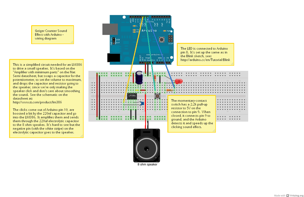
 A Geiger Counter Simulator Arduino Project Hub
 Soviet Russian Civil Defense Poster Geiger Counter Wiring Diagram Ebay Military Poster Civil Defense Education Poster


